Guidelines for Using the Database
Here we describe how you can access the data you are looking for and what the datasets actually look like.
Review the description of the GraVent explosion channel for information on the geometrical configurations and mixtures that have been investigated. Currently, this includes experiments in H2-air mixtures with homogeneous and inhomogeneous H2 distributions (transverse concentration gradients) in 10 geometrical configurations as well as experiments with water mist injection.
Needless to say, we want to make sure that the data is interpreted correctly. You will find some guidelines for data interpretation below. However, this guide cannot be exhaustive since it takes some experience with the particular experiment to say whether an effect that you see in the data is really physically meaningful or biased by some characteristics of the experiment. Therefore, we strongly encourage you to contact us if you see effects in the data that seem unexpected. We are happy to provide support.
How to get the Data
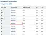
Fist of all you decide which type of experiment (e.g. homogeneous H2-air mixture) and which geometrical configuration (e.g. BR00) you are interested in. You go to the database and select the download for the average H2 concentration (e.g. 30 vol. %) you want to look at, cf. Fig. G.1.
Hitting the download button will start the download of all measurements available for your H2 concentration. You will obtain a zip file with this data that looks like Fig. G.2. in the case of the example BR00, homogeneous, 30 vol. %. You will see three experiments in this case. The data of each experiment is provided in an *.xls file. The file name contains our internal experiment number, blockage ratio, obstacle spacing, average H2 concentration and diffusion time (to identify the concentration gradient if relevant). In addition, a *.jpeg file provides a quick overview of flame speed data if available for the specific experiment.
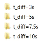
In the case of concentration gradient measurements, your download folder will contain subfolders named according to the diffusion times identifying the concentration gradients, cp. Fig. G.3.
Optical data is similarly organized. Each download contains all the optical data available for the specific configuration and H2 concentration you selected. Explanation of the interpretation of the data is given in a *.txt file located in the folder.
What a Dataset Contains
Each *.xls file contains three spreadsheets: Information; Flame speed; Overpressure. The structure of all *.xls files is the same so that you can access larger amounts of experiments easily with a VBA macro, for example.
The information sheet provides general information on the experiment such as geometry and mixture parameters.
The flame speed sheet provides flame speed over channel distance. This is a result of our photodiode measurements.
The overpressure sheet provides overpressure traces from up to 8 pressure transducers. The location of each transducer is also given here.
How to Interpret the Data
When interpreting the data you should be aware of some phenomena that are inherent to the applied measurement techniques:
Photodiodes:
Especially in lean mixtures and very slow experiments the signals recorded by the diodes are often not strong enough to determine flame arrival. In such cases, you might not find any flame speed data in the datasets.
The accuracy of the photodiode measurements can only be guaranteed at flame speeds below about 1000 m/s. Beyond 1000 m/s, you might observe strong oscillations in measured velocity which are typically not physically meaningful. Do not over-interpret such experimental results. It might be more accurate to evaluate arrival times at pressure transducers for velocity measurement since the dynamic response of the transducers is more accurate. Also, if you observe inexplicable single spikes in a flame speed plot also at lower flame speed do not over-interpret this. Such spikes may be caused by contaminants on a photodiode from previous experiments. If you need help with the interpretation, please contact us.
Pressure transducers:
Pressure transducer signals may be influenced by so-called thermal shock. This effect typically occurs when the reaction zone passes a transducer and rapidly heats up the transducer diaphragm. It heats up quickly due to its low thermal capacity, whereas the transducer housing heats up much more slowly. This reduces the piezo crystal preload and leads to measured pressure values below the real physical value. It especially affects the long-term behavior since the effect builds up over time. Pressure can easily become negative behind the maximum pressure peak at a transducer due to thermal shock. We try to prevent this by coating the transducers with high temperature grease. However, many experiments show thermal shock at single transducers. Please be aware of this when you analyse the data.
In our post-processing of the pressure transducer signals, a lowpass butterworth filter with a cut-off frequency of 45 kHz is applied to suppress amplitude overprediction due to the dynamic response of the transducers. This is an important step since higher frequencies, approaching the transducer eigenfrequency of 150 kHz, would lead to a strong response of the transducer and an amplitude overprediction. The 45 kHz cut-off frequency allows us to limit the overprediction to a maximum of 110 % of the real value. The pressure traces in the datasets are already filtered. If you want to compare the data with numerical simulations, the numerical data acquisition rate should be the same.


